Dynamic Force Analysis
Table of contents
Dynamic force analysis enables an engineer to understand more about the forces internal to the mechanism being investigated. This information can be used to improve the design and ensure that it achieves engineering targets.
There are a number of approaches that may be employed for dynamic force analysis however we will be focussing on only one, making use of Newton’s law as defined below in translation.
\[\sum\mathbf{F}=m\mathbf{a} \nonumber\]and rotation
\[\sum\mathbf{T}=I_g\alpha \nonumber\]The above equations must be written out for each of the moving bodies in the system which result in a system of equations that can be solved for the unknowns. Typically the weight of the members is ignored since they are often (but not always) negligible compared with the forces imposed on the system as a consequence of its motion (acceleration).
The general approach to a dynamic force analysis is;
- Draw a diagram of the system and each of its members, noting on each of the members the coordinate system(s).
- Isolate each of the members of the system drawing a free body diagram and noting on this the forces and torques applied to each of the members.
- Write out the equations of motion for each of the members and assemble these as a system of equations in matrix form.
- Finally, solve the matrix using an appropriate method for the unknowns.
Note that it is often the case that more information about the system will be required to complete the dynamic force analysis, for example the mass, mass moment inertia, angular position and angular speed of the links.
Single Link in Pure Rotation
We will be deriving a system of equations that enable us to calculate forces and torque in a single link undergoing pure rotation.
We are interested in knowing the forces in the single joint and the torque applied, given that we know the length, mass, mass moment of inertia, angle, angular velocity, accelerations and force applied to the link. Therefore, with reference to the diagram below we know the following; $\mathbf{R_{12}}$, $\mathbf{R_{p}}$, $m_2$, $I_{G2}$, $\theta_2$, $\omega_2$, $\alpha_2$, $\alpha_{G_2}$ and $F_P$.
The forces, $F_{12x}$ and $F_{12y}$ as well as the torque, $\mathbf{T_{12}}$ are unknown and this is what we will be calculating. We assume that all unknown forces and torques are positive in direction.
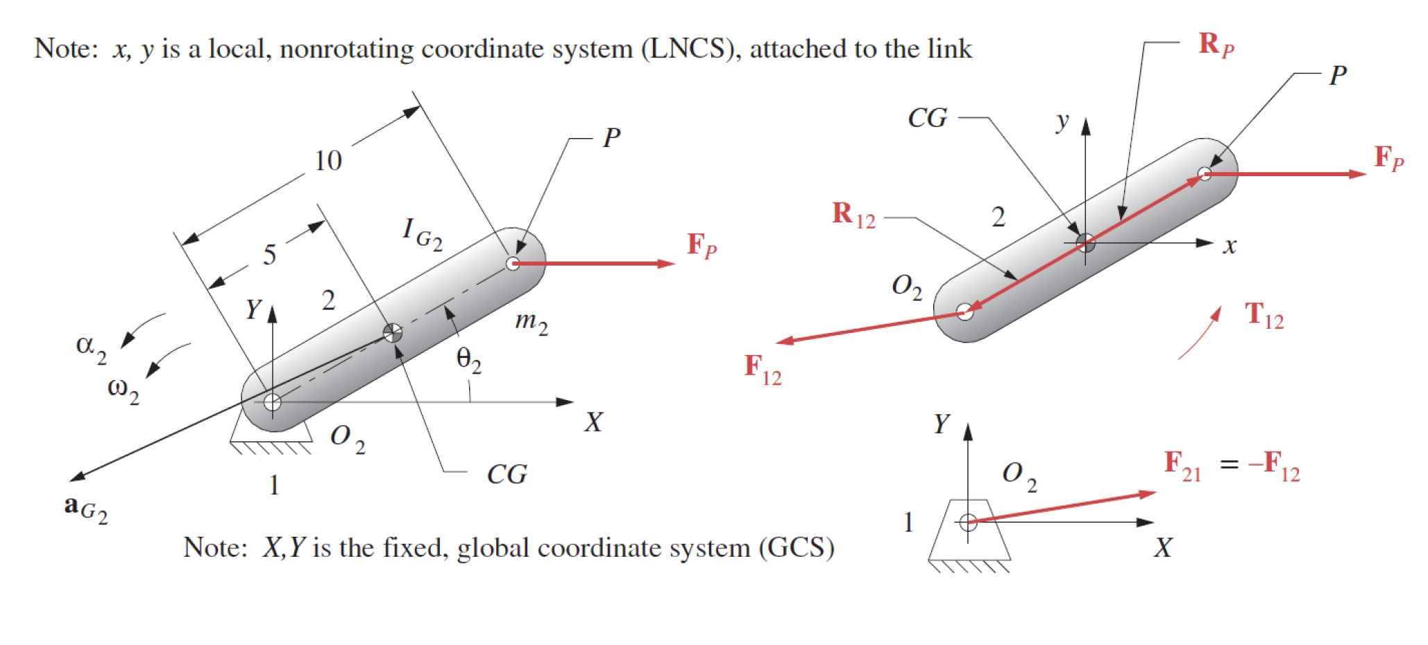
We choose a non-rotating local coordinate system located at the Centre of Gravity (CG) of the link and draw a Free Body Diagram (FBD) as shown in (b) of the figure above.
Note the forces, $\mathbf{F_{12}}$ and $\mathbf{F_p}$ and their point of application, $\mathbf{R_{12}}$ and $\mathbf{R_p}$ respectively.
Note also that there is a Torque, $\mathbf{T_{12}}$ applied to the link at the joint in the counter-clockwise (positive) direction.
We know that we have three unknowns and three equations which means the system can be solved.
Writing out the system of equations.
\[\sum \mathbf{F}=\mathbf{F}_P+\mathbf{F}_{12}=m_2 \mathbf{a}_G \\ \sum \mathbf{T}=\mathbf{T}_{12}+\left(\mathbf{R}_{12} \times \mathbf{F}_{12}\right)+\left(\mathbf{R}_P \times \mathbf{F}_P\right)=I_G \alpha \nonumber\]Expanding the above remembering that,
\[\mathbf{R} \times \mathbf{F} = (R_x \cdot F_y) - (R_y \cdot F_x) \nonumber\]the system of equations become
\[\begin{align*} F_{Px} &+ F_{12x} = m_2 a_{Gx} \\ F_{Py} &+ F_{12y} = m_2 a_{Gy} \\ T_{12} &+ \left(R_{12x} F_{12y} - R_{12y} F_{12x}\right) + \left(R_{Px} F_{Py} - R_{Py} F_{Px}\right) = I_G \alpha \end{align*}\]Putting the equations in matrix form.
\[\left[\begin{array}{ccc} 1 & 0 & 0 \\ 0 & 1 & 0 \\ -R_{12y} & R_{12x} & 1 \end{array}\right] \left[\begin{array}{l} F_{12x} \\ F_{12y} \\ T_{12} \end{array}\right]=\left[\begin{array}{l} m_2 a_{Gx}-F_{Px} \\ m_2 a_{Gy}-F_{Py} \\ I_G \alpha-\left(R_{Px} F_{Py}-R_{Py} F_{Px}\right) \end{array}\right] \nonumber\]Note that the first matrix on the left contains all of the geometric information about the system and the matrix on the right contains all of the information about the dynamics.
The values of $F_{12x}$, $F_{12y}$ and $T_{12}$ may now be calculated.
Single Link in Pure Rotation - Matlab Code
The following MATLAB code may be used to calculate the unknown values.
1
2
3
4
5
6
7
8
9
10
11
12
13
14
15
16
17
18
19
20
21
22
23
24
25
26
27
28
29
30
31
32
33
34
35
% Given scalar parameters
m2 = ; % Mass of the link
IG = ; % Mass moment of inertia
R12x = ; % x-coordinate of the distance from CG of the link to joint
R12y = ; % y-coordinate of the distance from CG of the link to joint
Rp_x = ; % x-coordinate of the distance from CG of the link to force application point
Rp_y = ; % y-coordinate of the distance from CG of the link to force application point
FPx = ; % Force applied along x-axis
FPy = ; % Force applied along y-axis
aGx = ; % Acceleration of CG of the link along x-axis
aGy = ; % Acceleration of CG of the link along y-axis
alpha = ; % Angular acceleration

% Coefficient matrix
A = [1, 0, 0;
     0, 1, 0;
     -R12y, R12x, 1];

% Right-hand side of the equations
rhs = [m2 * aGx - FPx;
       m2 * aGy - FPy;
       IG * alpha - (Rp_x * FPy - Rp_y * FPx)];

% Solve the system of equations
unknowns = A \ rhs;

% Extracting the unknowns
F12x = unknowns(1);
F12y = unknowns(2);
T12 = unknowns(3);

% Display the results
disp(['F12x = ', num2str(F12x)]);
disp(['F12y = ', num2str(F12y)]);
disp(['T12 = ', num2str(T12)]);
Four-Bar Crank-Slider Linkage
A four-bar crank-slider consists of ground link 1, crank 2, connecting link 3 and slider 4. The position, velocity and acceleration analysis must be completed first because the dynamic force analysis requires the mass-centre accelerations and angular accelerations of the moving links.
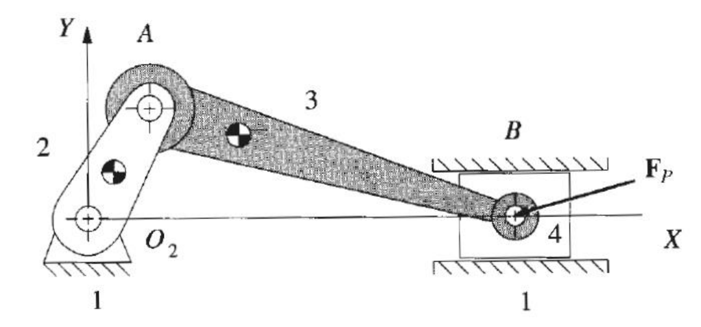
The analysis uses a common nonrotating $xy$ coordinate system. The known quantities are the link geometry and position vectors, $m_2$, $m_3$, $m_4$, $I_{G2}$, $I_{G3}$, the mass-centre accelerations, $\alpha_2$, $\alpha_3$, and the applied slider force $\mathbf{F}_P$. Slider 4 translates without rotating, so $\alpha_4=0$.
The nine unknowns are the four joint-force vectors $\mathbf{F}_{12}$, $\mathbf{F}_{32}$, $\mathbf{F}_{43}$ and $\mathbf{F}_{14}$, together with the actuator torque $T_{12}$:
\[[B]= \begin{bmatrix} F_{12x}&F_{12y}&F_{32x}&F_{32y}&F_{43x}&F_{43y}&F_{14x}&F_{14y}&T_{12} \end{bmatrix}^{T}.\]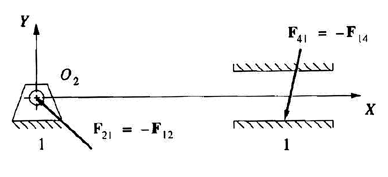
The notation $\mathbf{F}_{ij}$ denotes the force exerted by link $i$ on link $j$. At the shared pins, Newton’s third law gives
\[\mathbf{F}_{21}=-\mathbf{F}_{12}, \qquad \mathbf{F}_{23}=-\mathbf{F}_{32}, \qquad \mathbf{F}_{34}=-\mathbf{F}_{43}, \qquad \mathbf{F}_{41}=-\mathbf{F}_{14}.\]Using the same unknown force vector with the opposite sign on the adjoining link avoids introducing duplicate unknowns.
Link 2: Crank
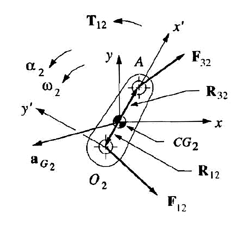
Crank 2 contributes two force equations and one moment equation. Taking moments about its mass centre $G_2$ gives
\[\begin{aligned} F_{12x}+F_{32x} &= m_2a_{G2x}, \\ F_{12y}+F_{32y} &= m_2a_{G2y}, \\ T_{12} +\left(R_{12x}F_{12y}-R_{12y}F_{12x}\right) +\left(R_{32x}F_{32y}-R_{32y}F_{32x}\right) &=I_{G2}\alpha_2. \end{aligned}\]The position vectors $\mathbf{R}_{12}$ and $\mathbf{R}_{32}$ run from $G_2$ to the points where $\mathbf{F}_{12}$ and $\mathbf{F}_{32}$ act.
Link 3: Connecting Link

The force exerted by link 2 on link 3 is $\mathbf{F}_{23}=-\mathbf{F}_{32}$. The Newton-Euler equations for link 3 are
\[\begin{aligned} F_{43x}-F_{32x} &= m_3a_{G3x}, \\ F_{43y}-F_{32y} &= m_3a_{G3y}, \\ \left(R_{43x}F_{43y}-R_{43y}F_{43x}\right) -\left(R_{23x}F_{32y}-R_{23y}F_{32x}\right) &=I_{G3}\alpha_3. \end{aligned}\]Here $\mathbf{R}_{23}$ and $\mathbf{R}_{43}$ run from $G_3$ to the crank pin and slider pin respectively.
Link 4: Slider
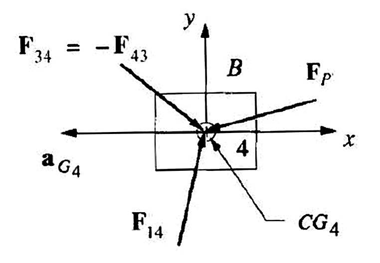
Slider 4 is acted on by $-\mathbf{F}_{43}$, the guide reaction $\mathbf{F}_{14}$ and the applied force $\mathbf{F}_P$. Its force equations are
\[\begin{aligned} F_{14x}-F_{43x}+F_{Px} &= m_4a_{G4x}, \\ F_{14y}-F_{43y}+F_{Py} &= m_4a_{G4y}. \end{aligned}\]For the ideal frictionless horizontal guide used in Lecture 3,
\[F_{14x}=0, \qquad a_{G4y}=0.\]The slider does not rotate. Because the forces shown act through $G_4$, its moment equation reduces to $\sum M_{G4}=I_{G4}\alpha_4=0$ and does not add an independent unknown.
Assembled Matrix System
Keeping the equations in the order introduced above and adding the guide constraint as the final row gives
\[\begin{bmatrix} 1 & 0 & 1 & 0 & 0 & 0 & 0 & 0 & 0 \\ 0 & 1 & 0 & 1 & 0 & 0 & 0 & 0 & 0 \\ -R_{12y} & R_{12x} & -R_{32y} & R_{32x} & 0 & 0 & 0 & 0 & 1 \\ 0 & 0 & -1 & 0 & 1 & 0 & 0 & 0 & 0 \\ 0 & 0 & 0 & -1 & 0 & 1 & 0 & 0 & 0 \\ 0 & 0 & R_{23y} & -R_{23x} & -R_{43y} & R_{43x} & 0 & 0 & 0 \\ 0 & 0 & 0 & 0 & -1 & 0 & 1 & 0 & 0 \\ 0 & 0 & 0 & 0 & 0 & -1 & 0 & 1 & 0 \\ 0 & 0 & 0 & 0 & 0 & 0 & 1 & 0 & 0 \end{bmatrix} \begin{bmatrix} F_{12x} \\ F_{12y} \\ F_{32x} \\ F_{32y} \\ F_{43x} \\ F_{43y} \\ F_{14x} \\ F_{14y} \\ T_{12} \end{bmatrix} = \begin{bmatrix} m_2a_{G2x} \\ m_2a_{G2y} \\ I_{G2}\alpha_2 \\ m_3a_{G3x} \\ m_3a_{G3y} \\ I_{G3}\alpha_3 \\ m_4a_{G4x}-F_{Px} \\ m_4a_{G4y}-F_{Py} \\ 0 \end{bmatrix}.\]For the horizontal guide, $a_{G4y}=0$, so the eighth right-hand-side entry becomes $-F_{Py}$. The coefficient matrix contains the known geometry and guide constraint, while the right-hand side contains the known inertia and applied-force terms. Solving the system gives the joint forces, guide reaction and required actuator torque at one instantaneous mechanism position.
Four-Bar Crank-Slider Linkage - MATLAB Code
The following MATLAB template assembles the same unknown vector and $9\times9$ system used above.
1
2
3
4
5
6
7
8
9
10
11
12
13
14
15
16
17
18
19
20
21
22
23
24
25
26
27
28
29
30
31
32
33
34
35
36
37
38
39
40
41
42
43
44
45
46
47
48
49
50
51
52
53
54
55
56
57
58
59
60
61
62
63
64
% Known mass properties
m2 = ;       % Mass of crank 2
m3 = ;       % Mass of connecting link 3
m4 = ;       % Mass of slider 4
IG2 = ;      % Centroidal mass moment of inertia of link 2
IG3 = ;      % Centroidal mass moment of inertia of link 3

% Position vectors measured from the relevant mass centre [x; y]
R12 = ;      % From G2 to the ground pin
R32 = ;      % From G2 to the link 2-link 3 pin
R23 = ;      % From G3 to the link 2-link 3 pin
R43 = ;      % From G3 to the link 3-link 4 pin

% Known applied force on slider 4
FPx = ;
FPy = ;

% Known mass-centre accelerations
aG2x = ;
aG2y = ;
aG3x = ;
aG3y = ;
aG4x = ;
aG4y = 0;   % Horizontal guide constraint

% Known angular accelerations
alpha2 = ;
alpha3 = ;

% Unknown order:
% [F12x F12y F32x F32y F43x F43y F14x F14y T12]'
A = [1, 0, 1, 0, 0, 0, 0, 0, 0;
     0, 1, 0, 1, 0, 0, 0, 0, 0;
     -R12(2), R12(1), -R32(2), R32(1), 0, 0, 0, 0, 1;
     0, 0, -1, 0, 1, 0, 0, 0, 0;
     0, 0, 0, -1, 0, 1, 0, 0, 0;
     0, 0, R23(2), -R23(1), -R43(2), R43(1), 0, 0, 0;
     0, 0, 0, 0, -1, 0, 1, 0, 0;
     0, 0, 0, 0, 0, -1, 0, 1, 0;
     0, 0, 0, 0, 0, 0, 1, 0, 0];

rhs = [m2 * aG2x;
       m2 * aG2y;
       IG2 * alpha2;
       m3 * aG3x;
       m3 * aG3y;
       IG3 * alpha3;
       m4 * aG4x - FPx;
       m4 * aG4y - FPy;
       0];

% Solve the simultaneous equations
unknowns = A \ rhs;

% Extract the joint-force components and actuator torque
F12x = unknowns(1);
F12y = unknowns(2);
F32x = unknowns(3);
F32y = unknowns(4);
F43x = unknowns(5);
F43y = unknowns(6);
F14x = unknowns(7);
F14y = unknowns(8);
T12  = unknowns(9);